CERES GOLF AND LIVING ESTATE INTRODUCTION TO THE GENERAL GUIDELINES : DRAFT 2 The General Guidelines are applicable to all homes to be constructed within the Ceres Golf and Living Estate, and in the case of certain erven, are expanded in terms of a Specific Guideline applicable to that particular erf. In general, a Specific Guideline will pertain building lines and driveways, but may cover other factors. In respect of certain erven, they will have wider design implications.
To achieve the above objectives the following aspects are addressed:
1. BUILDING FORM
Building form shall consist of the main building structure, which is expressed as a core building with abutments; and/or a free-standing structure. 1.1 MAIN BUILDING STRUCTURE (CORE BUILDINGS) 1.1.1 Building form must conform to the traditional "letter
of the alphabet" building types, which originated in the local
vernacular of the Cape. |
|
|
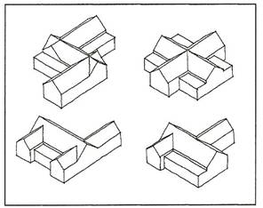 Figure 2 : Illustration of different building forms |
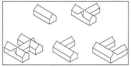
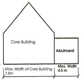
1.1.3 Rectangular sections of the core buildings must be built perpendicular to each other. 1.1.4 Buildings must be dimensioned as described further in this document. 1.1.5 In order to create larger floor plans than who's which building dimensions of the core buildings would allow, the plan forms may be extended in various combinations of ways by abutments. 1.2 ABUTMENTS 1.2.1 Abutments are rectangular, single storey extensions to core buildings. 1.2.2 Abutments must be built to the dimensions that are provided in this document. |
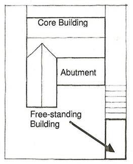 |
Figure 3 : Core Buildings with |
|
1.3 FREE-STANDING BUILDINGS 1.3.1 Free-standing buildings may have flat roofs. Up to two free-standing structures will be permitted. 1.3.2 Free-standing buildings may have a total maximum size of 70 m2, measured to the outside of the walls. 1.3.3 Free-standing buildings may not exceed 4,5m in width. |
|
2. BUILDING DIMENSIONS (WIDTH, HEIGHT & LENGTH)
|
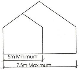 |
Figure 4 : Building widths: Core Buildings |
|
2.1 BUILDING WIDTH 2.1.1 Building Width of Core Building:i) TYPE I Erf: 5m - 7.5m ii) TYPE II Erf: 4.2m - 6.6m |
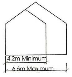 |
Figure 5 : Building widths: Core Buildings |
|
2.1.2 Building Width of Abutments The width of any abutment to the core building may not exceed 4.5 metres. (Figure 6)
2.1.3 Height and Width of Porticoes and Covered Entrances Porticoes, covered entrances, linking walkways and single free-standing buildings. may be narrower than the prescribed minimum width of a core building and are left to the architect's discretion. |
2.2 BUILDING HEIGHT The height of any building is related to its width, and the type of erf upon which it is built. 2.2.1 Core Building i) TYPE I Erf: |
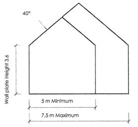 |
Figure 9 : Illustration of prescribed height for Type I Erf building |
ii) TYPE II Erf: |
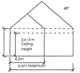 |
Figure 10 : Illustration of prescribed
height for Type II Erf building |
(i) On a Type I erf, where core buildings are 3.6m high measured to the wall plate level, the length of an abutment may be a maximum of 3.6 metres above finished floor level. (Figure 11) |
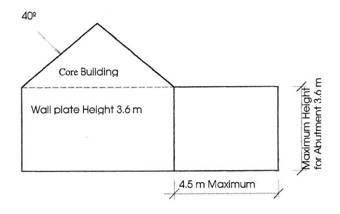 |
Figure 11 : Illustration of abutments
to core building |
| (ii) On a Type II erf,
where core buildings are higher than 3.6m measured
to the wall plate level, the height of abutments are to be according
to the discretion of the architect, but may not exceed 4.0 m, and
may not exceed the actual height of the wall plate level of the core
building, should it be less than 4.0m 2.2.3 Height of Free-standing Structures |
The provision of these guidelines lend themselves ideally to the utilization of the roof space for loft spaces, by virtue of the fact that the minimum wall plate height is specified as 3.6m above finished floor level and the maximum wall plate level height at 4.8m. Ventilation, light and views can be provided by the following methods:
3.1 CLERESTORY AND VENTILATOR WINDOWS Ventilator windows may be used under the eaves (see section 13 Windows and doors). 3.2 BARGED GABLES AND GABLE WINDOWS (a) The barged gable end walls of the letter of the alphabet type buildings create opportunities for the use of gable windows. These windows must be rectangular, (see section 12 Exterior Walls, Windows and Plaster bands, and section 13 Windows and doors). (b) On a flat main facade facing the street more than only one centre gable with window may be included. (c) Upper windows in gables may not exceed 1 250 mm in width (see also clause 13.1.1). (d) The height of the gable, as measured from the top of the eaves, may not be less than two thirds of the height of the roof of the core building, as seen on elevation, and the height of the wall plate may not be more than that of the core building.
3.3 DORMERS "French" dormers may be used on the facade on the private
side of the house that does not face the Street or a Close. They
may face a neighbouring erf or an Open Space if set back a minimum
of 7,5m from the boundary (see clause 13 Windows and Doors). Open
Space being defined as a natural environment at least 20m wide. |
4.1 SLOPES Building in slopes must be designed with stepped levels in response
to the slope of the site or on stepped building platforms. 4.2 GUIDELINES FOR THE BUILDINGS ON SLOPES The following provisions must be applied or buildings, which are situated on slopes: 4.2.1 The height of ground fill at any point
on the site may not be higher than 1.2m, measured from the natural
ground level at that particular point of the site. i) All retaining structures must be solidly built walls. ii) Vertical retaining structures on all boundaries must be stone. |
5.1 TYPE I Erf: maximum 60% 5.2 TYPE II Erf: maximum 50% but erven less than 450m2, 66%. The minimum allowable floor area of a unit is 120 m2. |
Differentiation must be made between two types of building lines,
namely: 6.2 Type B: This type of building line indicates the line on which the entire outer acade wall of a particular building structure must be built. |
|
7.1 DOORS GENERAL Door materials and colours are more fully detailed in section 15 Exterior Colours. Garage door openings must be 2 440mm wide. 7.2 DOUBLE GARAGES A double garage must comprise two garage doors next to each other separated by a 270mm - 470mm wide brick column, plastered and painted. In the event that a pergola or flat roof structure to a single garage is constructed, the parapet wall may not be arched unless a central column facing the street is provided. Parapet walls other than those facing the street may not be arched under any circumstances. No elevation may be provided with more than three columns, including the corner columns, and all columns of the structure must be of equal height. This structure must be attached to the core building, and a parapet wall of between 400mm and 800mm in height must surround the other three sides. 7.3 ADDITIONAL GARAGES Additional garages will only be permitted on certain erven. |
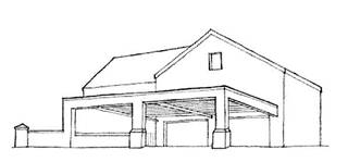 |
Figure 15 : Type I Erf Garages with pergola |
7.4 GARAGE DOORS ON STREET FRONTS
(EXCLUDING CLOSES) |
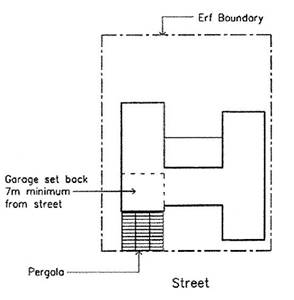 |
Figure 16 : Type I Erf showing double garage with carport and pergola |
7.4.2 Type II erven i) Garage doors are not permitted on a street boundary. A "poort" or archway wall on the street boundary can provide access to a garage positioned at least 4.5 metres away from the street boundary . Inward opening double leaf timber doors or metal gates are permitted. (Figure17) ii) A pergola or flat roof structure providing parking space in front of the garage must be constructed. |
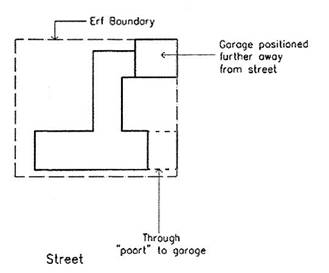 |
Figure 17 : Type II Erf showing 'poort' to garage. |
7.5 GARAGES ON A CLOSE These garages need not necessarily be separated from the close by a "poort" or archway wall, as specified in 7.4.2. If situated as described here, the garage doors, when open, must not extend beyond the erf boundary. Since there is no compulsory provision for the set back of garages in the case of a close, the design must in all cases provide a demarcated visitor's parking bay within the erf boundary, which may result in need to set the garage back from the erf boundary. 7.6 GOLF CARTS In terms of the Estate Rules, golf carts may not be parked in an area visible from the outside of an erf. Provision must therefore be made to accommodate them in a garage or elsewhere on the erf in conformity with this rule. 7.7 PARKING Parking space, including garages, must be provided for 3 vehicles in case of a Type I erf, and 2 vehicles in case of a Type II erf. |
|
8.1 ROOF CONSTRUCTION: 8.1.1 Only double pitched roofs are allowed on the core buildings. 8.1.2 The roof pitch of core buildings must be 40º. All double-pitched roofs must be symmetrical at the barged gable ends. 8.1.3 Gable walls may not project above the roof surface in which case the roof covering must be carried over the head of the wall to form a verge barge board, as the sloping edge of the roof is called 8.1.5 Roof material for pitched roofs. The same roof material is to be used for all visible pitched roofs
on a particular erf per dwelling. (ii) Charcoal colour natural slate tiles. No slate with any colour stains may be used. Achromatic (colourless silver pigmentation) will be permitted. (iii) Charcoal colour 'Armatile' tiles. 8.1.7 Gutters and Down pipes White or charcoal colour pre-painted O-gee shape seamless aluminium gutters are permitted. Down pipes are to be 70 mm diameter round aluminium in white colour or painted to match the colour of the walls. Chains will also be allowed. 8.2 FLAT ROOF CONSTRUCTION: FREE-STANDING GARAGES, CARPORTS & OUTBUILDINGS 8.2.1 Only flat roofs with minimum gradient falls with parapet walls on all sides and box gutters will be allowed for free-standing garages, carports and outbuildings. For the purpose of these guidelines, a flat roof shall be one with a gradient of between 1º and 8º. 8.2.2 Roof materials for flat roofs. The following materials may be considered: (i) Metal roof sheeting with, charcoal
colour paint finish or pre-painted charcoal colour finish. (iii) Skylights may be used to permit light into interior spaces. 8.3 ROOFS TO ABUTMENTS AND STOOPS Where the verge of roofs to abutments and stoops are exposed, they must have a minimum gradient of 15º. Flat roofs with a pitch of between 1º and 8º may be used. Curved Victorian Style roofs are not permitted. |
9. STOOPS AND VERANDAS (TYPES
I AND II ERVEN) 9.1 FRONT STOOPS AND VERANDAS A front stoop is a stoop constructed on a building, facing a street, close, the golf course, or other open space areas. For the purposes of these guidelines, a stoop which is covered by a pergola or a roof is referred to as a veranda. Front stoops must be provided along entire longitudinal walls facing a street or close on Type II erven on a flat facade, except where the facade incorporates a protruding gable. 9.1.1 The front stoop must be a maximum of 3 000 mm, and a minimum of 1 200 mm in depth. 9.1.2 These stoops may be uncovered or covered by a pergola or a lean-to roof creating a veranda.9.1.3 The roof structure of verandas may be exposed or a ceiling may be provided. Roofing material must be the same as that used for the roof of the core building of the house. 9.2 PRIVATE STOOPS AND VERANDAS These are stoops other than those dealt with in 9.1, constructed on the private side of the building, and internal to the erf. 9.2.1 The private stoop may be a maximum depth of 5 000 mm. 9.2.2 Private stoops may be covered with a lean-to roof with a gradient of 15º to 40º, if exposed on elevation, creating a veranda. 9.2.3 Alternatively, a pergola may be constructed on a private stoop, and approved timber poles may be used as covering. 9.2.4 Private stoops may be covered with flat roofs. 9.2.5 The roof structure of private verandas may be exposed or a ceiling may be provided. Other than in the case of 9.2.3 and 9.2.4, roofing material must be the same as that used for the main roof of the house. 9.2.6 STOOP/VERANDA/PERGOLA COLUMNS: 9.3.1 Columns to verandas and pergolas may be either cylindrical or square, but if facing a street or close, may only be square. 9.3.2 The finished plaster dimensions
of square columns with or without bases may not be less than
370 mm x 9.3.3 In the case of cylindrical steel columns, the diameter must not be less than 80 mm and not exceed 150 mm. 9.3.4 In the case of pergolas where a canvas roof is to be used, timber or steel may be used for the columns. 9.3.5 If pre-cast concrete columns are used, no copies of the Greek or Roman orders are permitted. The shaft of the column must be tapered and have a smooth surface and may therefore not be fluted. The diameter at the top must not be less than 220 mm and not exceed 330 mm at the base. 9.3.6 The top or capital of the column must be simple and not ornamented. Articulated bands, if used, must be limited to 3 bands of no more than 100 mm in height and 25 mm in depth. 9.3.7 No Victorian cast iron posts or "brookie lace" detail will be allowed. 9.3.8 No pre-cast concrete pipe sections combined to form columns will be allowed. |
10. BOUNDARY WALLS & PALISADES The Estate Rules will cover the policy towards keeping
domestic animals. 10.1 BOUNDARY DEFINITIONS For the purposes of the General and Specific Guidelines, the following types of boundaries have been defined. 10.1.1 Shared Boundary: Any single boundary, which separates two erven, or any two boundaries of separate erven, which are at any point situated less than 20 metres apart. These will generally run parallel, or almost parallel to each other. 10.1.2 Close Boundary/Street Boundary A boundary facing onto a close, defined in 10.1.3 Un-built Street or Close Boundary A boundary facing onto a street from a distance of less than 20 m at any point, from the road edge where no core building is built on the boundary or parallel to it. 10.1.4 Built Street or Close Boundary: A boundary facing onto a street or close form a distance of less the 20 m at any point away from the road edge, where a core building is built on the boundary or parallel to it, or within a few degrees of parallel to it. For the purpose of both 10.1.3 and 10.1.4 above, a boundary through which access to an erf is gained, although the street is further than 20 m away, shall be deemed to be facing onto a street. 10.1.5 Back Boundary: A boundary which is situated within 10 metres of the estate boundary, and which runs parallel, or within a few degrees of parallel, to the estate boundary. 10.1.6 Open Space Boundary A boundary facing onto any open space, such as golf course, river, or estate common area. As such it will not face a street, close or other erf boundary closer than 20 m away at any point from the boundary. (see 10.1.1) 10.2 GENERAL PROVISIONS IN RESPECT OF BOUNDARY WALLS 10.2.1 The provision laid out in these general guidelines apply to all erven, other than a Specific Guideline applicable to an erf is in conflict with them, in which case the provisions of the Specific Guidelines shall prevail. 10.2.2 The various permissible permutations relating to boundary walls, will include sub variations in certain categories, and will be detailed along with dimensions. The entire estate will be fenced with columns in between. 10.2.3 Boundary walls can incorporate saddle copings projecting no more than 25mm on either side of the wall. 10.2.4 The texture of the plaster finish to
all wall faces other than in cases of wall faces internal to the
erf must be wood trowelled, and if rough textured should conform
closely to the plaster finish to be found on walls at the entrance
of the estate. 10.2.5 All freestanding ends of walls must terminate in square columns 440mm x 440mm, with coping as detailed in 10.2.3. 10.2.6 Where walls incorporate columns, such columns must be square, must protrude no more than 100mm from the face of the wall, and incorporate copings as detailed in 10.2.3. All columns in all types of walls must be spaced a minimum of 3 500mm apart, measured centre to centre. 10.2.7 No wall may incorporate any recessed or raised panels, or any other form of embellishment, other than in the case of facade internal to the erf. 10.2.8 Any reference to the maximum height of a wall shall be taken as a measurement to the top of any coping forming part of the wall. 10.2.9 An opening in the wall for pedestrians, of a maximum width of 1200mm and a minimum width of 800mm may be provided. Any gate mounted in it must conform to clause 11 of these guidelines. 10.2.10 Palisades may be mounted on top of lower walls, with the coping permitted. The total height of these structures may not exceed 1.8m. 10.3 BOUNDARY WALL & PALISADE PROVISIONS FOR TYPE II ERVEN: The adjacent positioning of Type II erven effectively creates medium density clustered courtyard living spaces. 10.3.1 Shared Boundary No walling is obligatory. Owners should endeavour to achieve agreement on walls where they share a boundary. 10.3.2 Close Boundary: A wall may be built for the length of the boundary, and if desired for privacy, particularly for swimming pools, to a maximum of 1/3 of the length of the boundary. 10.3.3 Linking elements: Linking elements are encouraged and if employed, are defined to be part of facade structure, as opposed to a wall. 10.3.4 Open Space Boundary: 10.3.4.1 A steel palisade may be mounted
on top of a low wall in the open space boundary of an erf. to a
maximum total height of 1800mm. 10.3.4.3 Where palisades are used on top of a low wall, all balusters must be vertical, solid, and between 10mm x 10mm and 20mm x 20mm if square, and between 13mm and 20mm in diameter if round. No ornamental capping such as spear heads etc. will be permitted. 10.3.4.4 Where palisades are erected, but not a low wall, the palisade posts must be square, and of a minimum size of 70mm x 70mm and a maximum size of 100mm x 100mm. 10.4 BOUNDARY WALL & PALISADE PROVISIONS FOR TYPE I ERVEN: 10.4.1 Should an owner choose no boundary walls need be provide if no domestic animals require containment. 10.4.2 Shared Boundary: 10.4.2.1 Owners should endeavour to achieve agreement on walls where they share a boundary. 10.4.3 Un-built Street Boundary: The spaces between the core building and the boundaries on either side of it at right angles, or within a few degrees of right angles to it, must be closed of by construction of walls not necessarily positioned on the boundary itself, and if desired for privacy, particularly for swimming pools, a wall to a maximum of 1/3 of the length of the boundary may be errected. 10.4.4 Open Space Boundary: 10.4.4.1 Low Boundary walls may be used on the open space boundary of an erf. 10.4.4.2 A steel palisade may be mounted on top of low walls in the open space boundary of an erf to a maximum total height of 1800mm. 10.4.4.3 A steel palisade may be erected on the open space boundary of an erf, to a maximum total height of 1800mm, and if adjoining a shared boundary, the palisade must return 3 000mm on such shared boundary and must meet a column conforming with the guidelines for the type of wall in which it is set. 10.4.4.4 Where palisades are used, all balusters must be vertical, solid, and between 10mm x 10mm and 20mm x 20mm if square, and between 13mm and 20mm in diameter if round. Horizontal members required for structural purposes must match the size of the balusters. 10.4.4.5 Where palisades are erected, but not a type A wall, the palisade posts must be square, and of a minimum size of 70mm x 70mm and a maximum size of 100mm x 100mm. 10.4.4.6 Where palisades are erected atop a low wall, brick work and columns, conforming to the general condition laid down for the wall. 10.4.4.7 In such event, the total maximum height of 1800mm shall apply to the top of the palisade and the lower side of the column copings shall not extend more than 100mm above the top of the palisades. |
|
Either wrought iron, steel or timber gates with varnished or painted finish may be used. Linear patters of predominantly vertical rather than horizontal nature only may be used. |
12. EXTERIOR WALLS, WINDOW SILLS AND PLASTER BANDS 12.1 External walls must be plastered with a smooth wood trowel finish and painted (no articulated or un-even plaster will be permitted). 12.2 All external window sills and surrounds must be plastered with a smooth wooden trowel finish. 12.3 Simple articulated plaster bands are encouraged and if used, must have a minimum width of 120mm and a maximum width of 200mm. 12.4 Plaster bands with a minimum width of 120mm and a maximum width of 140mm to clerestory windows are permitted. |
13.1 WINDOWS Reference should also be made to Section 3 UTILIZATION OF THE ROOF SPACE in respect of ventilator windows, gable windows and roof windows. 13.1.1 Only windows in which the vertical dimension
exceeds the horizontal are allowed. Notwithstanding the provision contained above where projecting chimneys are positioned centrally in a gable, one window on either side of the chimney in a position above ground floor ceiling height will be permitted. 13.1.2 Notwithstanding the provision contained in 13.1 above, and with exception of gables, clerestory and ventilator windows may be located in the section of wall beneath the wall plate and above ground floor ceiling height, and may be of such a nature that the horizontal proportion exceeds the vertical. In such cases the maximum horizontal proportion is 900mm and the maximum vertical proportion 600mm. 13.1.3 Notwithstanding the provision contained in 13.1 above, in the case of type II erven only, certain other windows may be located in the section of wall beneath the wall plate and above ground floor ceiling height, other than in the case of a flat facade with no abutment or veranda. These windows must be 900mm in width, by either 1200mm or 1500mm and may be additional to clerestory windows dealt with in 13.1.2. A maximum of three of these windows may be used in the case of a flat facade with an abutment or veranda, or on the portion of a facade with a protruding gable. Where a central protruding gable is found, four windows will be allowed to ensure symmetry. One each may also be used on the side walls of the gable protruding from the main facade. 13.1.4 Where other than clerestory / ventilator windows are incorporated in a facade using "French Dormers" (see section 3.3 DORMERS), they may be used in the case of a flat facade with an abutment or veranda, or on the flat portion of a facade with a protruding gable. In cases as described above, the total opening width may not be more than 70% of the width of the French dormer. 13.1.5 'Winblok' or other pre-cast concrete windows, glass block windows, or leaded windows with diamond patterns or mock sash type windows (windows resembling a sash window but operating in any fashion other than vertical sliding) are not permitted. 13.1.6 Bay windows are permitted. 13.1.9 Coloured glass is not permitted in any window or door facing a street or close. 13.1.10 The combined width of all openings (doors & windows) per facade may be more than 50% of the total width of the facade. 13.1.11 The combined width of all openings (doors & windows) per BARGED GABLE END may be more than 50% of the total width of the BARGED GABLE END. 13.2 DOORS 13.2.1 Front doors facing a street or close boundary may not exceed 2 700mm in height, measured to the top of the fanlight if applicable. The maximum total width of the aperture may be 1 750mm in the case of double doors, and 1 200mm in the case of single doors. The mid-rail of the door, where applicable must be 700mm above finished floor level. 13.2.2 Any door other than the front door, sliding, folding or otherwise, fitted to openings exceeding 1750mm, measured to the total width of the opening, including sidelight, etc. must be placed at least 3500mm behind a veranda or pergola. 13.2.3 Barn type doors which must have double leaves, wooden shutters and arched tops are permitted in gables on ground floor only. 13.3 AWNINGS Awnings, of any material, fixed, retractable, or other, may not be mounted to, or above any window or door other than on the private side of the building, away from streets, closes, the golf course and other open space areas, and internal to the erf and may not be shiny. |
14.1 Shutters must be functional. No false shutters are permitted. 14.2 Shutters must be of hardwood or epoxy powder coated aluminium. 14.3 The surface finish and colour of the shutters must match that of the window frame over which they close. |
All surfaces for painting must be properly prepared, particularly in the case of metals, which must be galvanized to avoid rusting and degreased to avoid pain flaking. 15.1 Plastered exterior walls, including boundary walls and columns may be painted in the 'earth' colours determined by the architects. 15.2 Timber windows and doors
(excluding garage doors), shutters, 15.3 Timber garage doors must be painted either pure white or to match the colour of the wall in which they are mounted. 15.4 Aluminium garage doors must be epoxy powder coated in pure white or grey. 15.5 Aluminium frames, windows and doors must be epoxy powder coated in one of the colours prescribed in 15.2. 15.6 Plaster bands and window sills must be painted pure white, or to match the colour of the wall into which they are set. 15.7 Palisades, other than the brickwork which may support them, may be painted in one of the colours prescribed in 15.2, excluding white. 15.8 Wrought iron or steel gates must be painted matte black, or in one of the colours prescribed in 15.2. 15.9 Timber gates may be varnished or painted in one of the colours prescribed in 15.2. 15.10 Roofs, if painted, must be dark grey, white or charcoal. 15.11 Chimneys, as described in section 20, must be painted to match the wall to which they are attached. 15.12 Fascias and bargeboards must be painted pure white or to match the colour of the roof which they abut. 15.13 Gutters must be painted to match the fascias and down pipes must be painted to match the wall to which they are affixed. |
16.1 Balconies must form an integral part of the design and any visible sides of slabs, or brickwork, must be plastered and painted to match the wall surface to which they attach. 16.2 The following balcony types are permitted: 16.2.1 Type A The slab may protrude a maximum of 200mm from the exterior face of the building and the width of the balcony may not exceed 1750mm. A handrail must be fixed onto the side or top of the entire slab. The doors giving access to the balcony must open inwards. 16.2.2 Type B The slab may protrude a maximum of 1000mm from the exterior face of the building and the width of the balcony may not exceed 3000mm. A handrail must be fixed onto the side or top of the entire slab. The doors giving access to the balcony may open inwards or outwards. The supporting columns must conform to the general provision for columns contained in section 10.2 of these guidelines. In place of columns, a concrete "buttress" to support cantilever slabs may be used, structural or ornamental. 16.2.3 Type C Larger balconies are permitted, provided that the following conditions are complied with: 16.2.3.1 They may not by constructed on elevations aligning with a boundary of the erf concerned, which boundary fronts onto a street or close. Where they front onto a shared boundary, the front of the balcony may not be closer than 5m from the boundary. 16.2.3.2 They must be enclosed by the walls of the core buildings, abutting walls on all sides other than the front, and the slab may not extend beyond the walls against which it abuts. 16.2.3.3 A balustrade may be fixed on the side or top of the slab. 16.2.3.4 Alternatively, brickwork to a maximum height of 1000mm may be constructed on the edged of the slab and a handrail fixed on the sides or top of the brickwork. 16.2.4 Type D These balconies are accommodated only in gable front walls and
if employed will be the only aperture permitted in the gable above
ground floor ceiling height (no additional window permitted). 16.2.4.2 The aperture may not exceed 1/3 of the gable width, and the vertical proportions must be between 1.2 and 1.5 of the horizontal proportions. 16.2.4.3 Double leaf, inward opening doors must be fitted and if not natural timber, must match the exterior colour of the wall into which they are set. 16.2.4.4 A balustrade of colour matching door frames must be mounted in the aperture. |
The following conditions apply to handrails and balustrade: 17.1 The height of the top
of all handrails or balustrades, including those mounted on brickwork,
must be 1050mm above the floor finishes of the balcony slab. 17.3 Square mild steel tubing and flats, painted white or any of the colours prescribed in 15.2. |
18. BURGLAR BARS, SECURITY GATES AND SYSTEMS, INCLUDING SECURITY LIGHTS 18.1 All burglar bars, security gates and security screens, including expandable and sliding products, and roller shutter systems, must be mounted internal to the openings which they secure, behind the glazing of windows or sliding door and behind wooden doors. 18.2 Every effort should be made to align vertical bars with mullions. 18.3 Security lights may not cast direct light outside the erf upon which they are situated and must be activated by movement sensors. |
19.1 Television aerials and satellite dishes must be fitted below the main building eaves line. Satellite dishes must be white composite or approved equivalent. 19.2 Sewer and vent pipes must be concealed in vertical ducting within the wall plane of the building. 19.3 All telephone and electrical cable reticulation on the property must be underground. No overhead masts or wires are permitted. 19.4 Air-conditioning condenser units must, if not located within a service yard as prescribed in 10.5, be installed against exterior walls at or below ground level and must not exceed a height of 1200mm above ground level and must be entirely screened by a surrounding brickwork wall of finish and colour matching the exterior wall to which it is attached. If the condenser units are placed on a flat roof they must be entirely screened by a surrounding brickwork wall of finish and colour matching the exterior wall to which it is attached. The brickwork must extend a minimum of 200mm above the condenser
unit and may not be higher than the underside of the fascia. Window mounted air-conditioning units are not permitted. 19.5 House numbers must comply with a font approved by the architect. 19.6 Gas cylinders,
refuse bins, compost piles and clothes lines must be
located within service yards as prescribed in 10.5. |
|
Plastered and painted masonry and stone chimneys are permitted, strictly in accordance with the guidelines issued by the architects. The highest point of the chimney must be a maximum of 1000mm above the ridgeline of the roof. |
Lights on walls at the front door, garage or entrances form a welcome guide for visitors and play both a functional and aesthetic role. Other contemporary lighting designs may also be used. No coloured bulbs or glass to light fittings is permitted. |
Courtyards are among the most ancient of outdoor rooms. Of particular significance for Ceres Golf Estate is the opportunity created for courtyard living by the urban design of each development node with Type II erven. The establishment of courtyards is also encouraged for Type I erven. |
23.1 Visual privacy 23.1.1 The guidelines cannot guarantee visual privacy. The Home Owners Association will however, in applying the guidelines take great care that it is achieved to the maximum degree practically possible. 23.1.2 It is important that individual property owners ensure that houses are designed in a manner which respects the need for private outdoor space for neighbouring owners. 23.2 Noise 23.2.1 While visual privacy can be attained by providing screen walls and locating windows and balconies in areas where privacy of the next-door neighbours are not compromised, noise is a potential problem that must be managed. 23.2.2 Good neighbourliness requires noise levels to be kept low by individual households. 23.2.3 Measures are required to regulate and reduce noise levels through technical and design intervention; (i) The most effective way of reducing
noise disturbance is to ensure that outside living spaces of neighbours
are not located directly alongside one another, but that outdoor
spaces are located in the centre of an erf with a building separating
outdoor living spaces. (iii) Boundary walls can also be defined by covered walkways, which serve as linking elements between buildings and noise screening devices. (iv) The sound of falling water from water features located along boundary walls is an effective method of reducing noise from external sources. |
There are a number of ways of achieving edge continuity by linking facades of buildings which then define the street edge. The following are examples of such linking elements: 1. Archways, (sometimes closed with stable
like doors) or coachman's entrances. |
25.1 PLANT SPECIES PERMITTED 25.1.1 In order to integrate private gardens
with overall landscaping of the estate, it is recommended that
owners use: 25.1.2 Non-invasive exotic plants may be used. 25.1.3 Owners encouraged to use Buffalo or Kweek grass for lawn area as these grass types are less invasive and less water demanding than Kikuyu.
25.2 PLANT SPECIES NOT PERMITTED 25.2.1 All declared invasive alien plants listed in the "Conservation of Agricultural Resources Act, 1983", (Act No.43 of 1983) and subsequent amendments to Act NO. 43 of 1983 are not permitted within the estate and may not be cultivated in private gardens 25.2.2 It is necessary for an owner to submit a planting plan for his private garden 25.3 IRRIGATION OF PRIVATE GARDENS 25.3.1 Should irrigation systems be installed, owners must design them in such a way that they do not cause brown or other staining to any walls. 25.3.2 Owners may not connect their private irrigation systems into the estate's irrigation system.
25.4 MAINTENANCE OF PRIVATE GARDENS 25.4.1 All gardens are required to be kept in a tidy state at all times. 25.4.2 All erven on which no structures have yet been built must be mown on a regular basis. Any unit erf which is not mown on a regular basis will be maintained by the HOA and the cost thereof charged to the respective owner. 25.5 SITE ESTABLISHMENT PRIOR TO CONSTRUCTION 25.5.1 Should an owner require landscaping to be temporarily or permanently removed during the construction of his home or driveway, then he shall complete the Request Form, and submit it to the HOA. 25.5.2 In order to process the Request Form and implement the work timorously, the form must be submitted to the HOA a minimum of 10 working days before the work needs to be done. 25.5.3 No verbal instructions may be given to maintenance staff to remove landscaping. 25.6 EXISTING LANDSCAPING IN PUBLIC AREAS 25.6.1 Landscaping and irrigation have been installed in public areas. This landscaping and irrigation may not be altered or tampered with by an owner in any manner whatsoever. 25.6.2 Similarly, the cutting back of branches from trees in public area may not be undertaken by an owner. Should an owner require tree surgery to be undertaken on an existing tree, then the application process described in item 25.5 must be followed. Should a tree be damaged or cut back without the correct procedure having been followed, then the HOA may impose a fine on the owner. The amount of the fine is in the discretion of the HOA. 25.6.3 Where an owner elects not to build a boundary wall between his garden and the public area, he must ensure that the ground level of his garden ties in smoothly and neatly with the existing ground level of the public area to avoid steep level changes and soil erosion. In addition, where an owner wishes to establish a plant bed bordering on a public area that is lawned, the planter beds must be neatly edged. Should an edging be required, then the same brick as already in use in the public areas may be used. 25.6.4 No materials may be stored or dumped in public areas e.g. fire wood, building material or pot plants. 25.7 PAVING 25.7.1 The proposed type, colour and pattern
of all paving both: 25.7.2 All paved areas that are visible from outside the property must be harmonious with the paving used on the estate, (Cobblestone). On driveways cobbles must be used. Premix, cast insitu concrete, interlocking blocks and grass blocks may not be used. Pedestrian paths may be constructed from the clay or concrete pavers, paving slabs, stone chip or laterite. Paving slabs must be rectangular or square. 25.7.3 Natural, earthy paving colours may be
used. Grey and black materials are preferred. No driveway may be wider than 6m. Where the section of driveway between the road and erf boundary
exceeds 6m in length, the maximum driveway width is 3m. A pathway to the entrance of a house may not exceed 1,5m in width. A paved access for golf carts may not exceed 2m in width. A driveway, pathway and/or golf cart access may not be built adjacent to each other to form a continuous paved area. Driveways must join access roads at right angles except where an access road is 3m wide, and a larger turning circle into a driveway is required. In this instance, and at a distance of 1m from the road, the driveway may be splayed at a 45º angle. 25.7.5 The final level of paved areas must be flushed with existing levels to prevent soil erosion and exposed concrete hunching. Where the levels cannot be smoothly tied in, the level of the adjacent landscape should be raised or lowered through application to the HOA. 25.7.6 All paved area must be concreted as per standard building practices to ensure an even surface. All paving edges must also be laid evenly, flush with ground level, on a concrete footing and edge the entire length of the driveway/path. 25.7.7 Stone chip and laterite pathways must be edged with evenly laid bricks that are flush with ground level, on a concrete footing and around the total perimeter of the driveway/path. 25.7.8 Before an owner builds a driveway, he must notify the HOA so that they can install 110PVC sleeves in the driveway area. The sleeves are required to protect and accommodate the existing services in the public space and are installed 500mm below ground level. 25.7.9 No paving other than access between the erf boundary and road is permitted in public spaces. 25.7.10 Should an owner require a change to his existing driveway, then he shall complete the Request Form and submit to the HOA. 25.7.11 Similarly, where an owner: then the paving of the existing driveway must be removed and the
area reinstated to landscaping. The reinstated landscaping must
match the existing landscaping in the immediately surrounding area
i.e. if the existing landscaping consists of a mixed border of
plants, then it is not possible to change the theme to an orchard
or any other type of agricultural planting. 25.8 STORMWATER AND SUBSURFACE WATER 25.8.1 All owners must indicate on the site plan submitted to the HOA for approval how they are going to deal with storm water from roofs and paved areas and subsurface water. 25.8.2 All installation and connection of drainage
through public areas is to be done by the HOA. Listed below are
forms of drainage that the HOA will implement: Where the ground slopes sufficiently but there is no direct access
into the storm water system, then a 110mm PVC
pipe may be installed 500mm below ground into a concrete box built
adjacent to the storm water channel. Where water volumes are very low, 50mm PVC pipes may be built by the owner into his boundary wall. The pipes must be cut flush with the wall and be spaced 2m apart. The pipe outlet must be a maximum of 200mm above the ground level of the public area. Where water needs to be piped from an erf, through a public space to the river edge or wetland, the pipe will be installed. 25.8.3 Where an owner does not want rainwater to be dispersed naturally on his erf but wants to collect it directly from his roof and pipe it off his property, then he must inform the HOA. Water collected in this manner will be discharged directly into the nearest storm water inlet. 25.9 BOUNDARY WALLS 25.9.1 All boundary walls are to be plastered to a minimum of 100mm below the final ground level. In addition, the soil adjacent to walls must be compacted after plastering to avoid the unplastered brickwork becoming visible through soil erosion or subsidence. 25.10 POOLS 25.10.1 All pool water is to be discharged directly into the sewer system by the owner. The connection into the sewer system must be made on his property i.e. connection into the sewer system within public areas is not allowed. 25.11 PROCEDURE FOR IMPLEMENTATION OF CHANGES TO PUBLIC AREA LANDSCAPING 25.11.1 It is in the best interests of all owners for the standard of work and method of implementation in public areas to be the same throughout Ceres Golf Estate. Standardisation makes maintenance simpler and easier, product guarantees are assured and the quality of workmanship is consistent. In addition, there are many services - electrical cables, sewer pipes, potable water pipes, irrigation pipes - that are present in public areas. Damage of these services has far-reaching implications and therefore strict control of work around services is necessary. For the above reasons, only HOA personnel or the Estate's Landscape Representative may undertake work in public areas. The only exception is that an owner may install his own driveway. 25.11.2 Should an owner require a change to any public area landscape related item, he shall contact the HOA office and arrange a site meeting to identify the extent of work to be undertaken. This will be dated and detailed on the Request Form 25.11.3 All proposed changes are to be clearly highlighted on a site plan (drawn to scale) and attached to the Request Form for costing and record purposed. The form and plan must be submitted to the HOA office for approval. 25.11.4 The proposed changes will
be adjudicated by the HOA and if approved, the cost of undertaking
the work will be submitted to the owner for approval. A minimum
of 5 working days is required for the costing process. 25.11.6 From receipt of the signed form, a minimum of 5 working days is required before the implementation of changes will be undertaken. 25.11.7 All costs for the above changes are payable to the HOA. 25.11.8 Should an owner not follow the procedure given above and undertake the work himself, then the HOA has the right to redo the work in the correct manner at the owners cost.
25.12 ADDITIONAL LANDSCAPING TO PUBLIC AREAS 25.12.1 Should an owner believe
that the public area adjacent to his erf would benefit from additional
landscaping and he is prepared to pay for the implementation and
maintenance of the landscaping, he may submit an application to
the HOA. An irrigation plan must be submitted. 25.12.5 An agreement for the implementation and maintenance of the additional landscaping by the Estate's Landscape Representative must be entered into. The agreement will be renewable on an annual basis but may be cancelled at any time at the sole discretion of the HOA should the area not be used in the manner originally intended or should the owner fail to pay for the maintenance thereof. The HOA reserves the right to reinstate the area as it deems fit at the cost of the owner concerned. 25.12.6 All other owners will have access to the area with no restriction other than those already imposed by estate rules. 25.12.7 Only public areas belonging to the HOA may be included. Areas designated to the Golf Course will not be allowed. 25.12.8 Plans should not compromise or interfere with any existing estate services particularly water and electricity. Way leaves will have to be obtained by the Estate's Landscape Representative before commencement of work. 25.12.9 Work must be completed within one month of plan approval. |
26.1 General 26.1.1 No plans may be submitted to the local authority or competent body for its approval until scrutinized by the Home Owners Association's nominated architects. 26.1.2 Detailed procedural rules for submission and approval may be issued by the Home Owner's Association from time to time and must be strictly adhered to. 26.1.3 For the information required on drawings and the plan submission procedure, all design architects must visit the estate website. |
27. HOTEL 27.1 Proposed Development 27.1.1 The drawings and final design of the hotel on the northern side of Voortrekker Street, will be finalised once the final number (between 50 and 80) of rooms have been determined. The guidelines for this development are similar to the houses on the golf course. See attached plans and elevations. 27.1.2 Sufficient parking will be provided according to the zoning specifications and municipal regulations. 27.1.3 A modern gymnasium and possible indoor swimming pool will also be accommodated on the Hotel premises. |
28. CLUBHOUSE ON ESTATE 28.1 Upgraded & modern Clubhouse 28.1.1 The drawings and final design of the clubhouse are attached. 28.1.2 The guidelines for this development are similar to the houses on the golf course. |
29. ADDITIONAL RESIDENTIAL DEVELOPMENT 29.1 Town Houses 29.1.1 The drawings and proposed layout of the town house development on the north-western side of the estate are attached. 29.1.2 The guidelines for this development are similar to the houses on the golf course. |